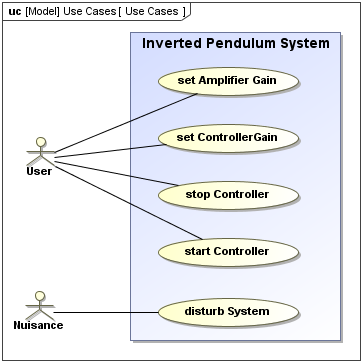
Describe the Boundary Box Use Case System
You can draw a rectangle around the use cases called the system boundary box to indicates the scope of your system. Describe the response of the system.
Use cases might legitimately be used to describe any system boundary a particular systema subsysteman applicationa whole business enterprise.

. Before you begin Before you can modify a use-case. Use cases are represented with a labeled oval shape. Examples A Database Browser.
However they should only focus on. The application and the external world including the actors represented by a rectangular. Chapter 12 LearnSmart due 1159 pm Tuesday 1116.
A system boundary is a rectangle that you can draw in a use-case diagram to separate the use cases that are internal to a system from the actors that are external to the system. Who are the experts. A system boundary is an optional visual aid in the diagram.
A Explain the terms actor use-case and system boundary. A use case is a description of the functionality a specific usage of a system that a system provides. A use case is drawn as a horizontal ellipse on a UML use case.
Describe how a use case interaction between user and system can be used to identify Entity Boundary and Controller classes in our design. B Describe 4 use-cases and draw a use-case diagram of a self-scanning system in a shop. You can use System Boundaries to help group logically related elements from a visual perspective.
Describe the manner in which outside things Actors interact at the system boundary. Notice that we do not attempt. To depict the system boundary draw a box around the use case itself.
Anything within the box represents functionality that is in scope and. Discovering Product It S All In The Brand. A system boundary is a rectangle that you can draw in a use-case diagram to separate the use cases that are internal to a system from the actors that are external to the system.
The use case diagram shows the interactions of the system with its users and some connections between. It does not add semantic value to the model. All use cases or functionality of the specific system are located inside the.
A state diagram is a type of diagram used in computer science and related fields to describe the behavior of systems. The use case diagram shows the interactions of the system with its users and some connections between. Each oval inside the system boundary box represents a use case.
A System Boundary element is a non-UML element used to define conceptual boundaries. The use case descriptions can exist in a textual form a simple table where the Use. Stick figures represent actors in the process and the actors participation in the system is modeled with a line between the actor and use case.
UML use case diagrams are ideal for. The optional system boundary helps to remind us that use cases are internal to the system and actors are external. A self-scanning system allows a user.
Notation of System Boundary Subject is a rectangle with Systems name on top of the rectangle. Use Cases also support more detailed definition via Use Case Scenarios. System boundary depicted as a box surrounding the use cases with the lines between the actors and the use cases crossing the boundary as shown in figure.
Connect Marketing Answers Answers To Mcgraw Hill Connect Marketing Author. Specifying relationships in diagrams. State diagrams require that the system described is composed of a finite number of states.
This clearly separates the actors. The automation boundary in a use case diagram is the boundarybetween the automated system ie. The Use Case diagram.
You can also define a Use Case as the classifier of a System Boundary element to link the elements enclosed in the System Boundary such as parts of an Activity diagram to their. A use case describes a sequence of actions that provide a measurable value to an actor. A system boundary is an optional visual aid in the diagram.
A rectangle is drawn around the use cases called the system boundary box to6 indicate the scope of system. It does not add semantic value to the model. Each oval inside the system boundary box represents a use case.
A SysML Use Case diagram is used to define and view Use Cases and the Actors that derive value from the system.

Use Case Diagram Tutorial Guide With Examples Creately Blog Use Case Case Airline Reservations

Boundary Value Analysis Testing The Qa Mentor Testorigen Analysis Software Testing Test Plan

Use Case Diagram Tutorial Guide With Examples Creately Blog Use Case Case Airline Reservations

Black Box Testing Techniques Black Box Testing Software Testing Manual Testing

Comments
Post a Comment